Radioulnar limb deformity correction - Max
Radioulnar deformity is one of the most common forms of angular limb deformity in dogs. The radius and ulna must grow together to maintain normal forelimb alignment. Premature closure of the distal ulnar physis can restrict ulnar growth while the radius continues to lengthen, resulting in relative shortening of the ulna and progressive deformity of the radius. This growth discrepancy can produce a combination of angulation, rotation and joint incongruity.
For this case, VetForge collaborated with Dr. Sarah Goldsmid and Dr. Kyle Song at Animal Referral Hospital to plan a patient-specific correction for Max’s radioulnar deformity.
Max had undergone a proximal ulnar osteotomy as a puppy to address elbow incongruity. Despite this earlier intervention, he remained lame with significant residual deformity. His forelimb exhibited excessive valgus, procurvatum and external rotation, together with subluxation of the humeroradial joint.
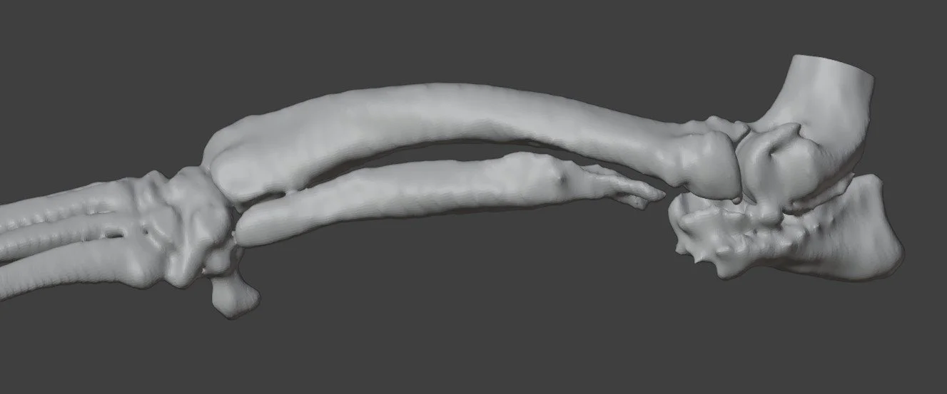
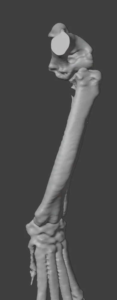
Image: Original limb model demonstrating the valgus, procurvatum and external rotation, together with humeroradial subluxation.
Planning Challenges: Addressing a Three-Dimensional Deformity
The principal challenge was defining a correction that accounted for all three components of Max’s deformity. Planning needed to consider how changes in angulation and rotation would affect the relationship between the proximal and distal bone segments, as well as the resulting alignment of the elbow and carpus.
Although CT and orthogonal radiographs provide essential anatomical information, translating a complex multidirectional deformity into the required osteotomy planes and final segment positions can be challenging.
Using computer-aided design (CAD), we planned a closing wedge osteotomy to improve alignment between the elbow and carpus. Three-dimensional modelling allowed the proposed correction to be visualised and assessed before developing the patient-specific surgical guides.
The planning process addressed two connected tasks: defining the location and orientation of the bone cuts, and establishing the intended position of the bone segments after the wedge was removed.
Video: Three-dimensional planning of Max’s radioulnar deformity correction, showing the original limb, planned osteotomy planes and closing wedge correction to address valgus, procurvatum and external rotation.
Osteotomy Guide: Translating the Plan to the Bone
A patient-specific osteotomy guide was designed to transfer the planned cutting planes to Max’s bone.
The guide incorporated the planned osteotomy geometry and trajectories for 1.6 mm fixation pins. These pin positions were considered alongside the subsequent reduction, linking the initial guide placement with the intended corrected alignment.
For a closing wedge osteotomy, both the position and orientation of the cuts determine the segment being removed. The guide provided a physical reference for reproducing these cuts and connecting the digital plan with the surgical procedure.
Shown on the original bone model, the guide illustrates how its positioning relates to Max’s individual anatomy and the planned radial wedge.
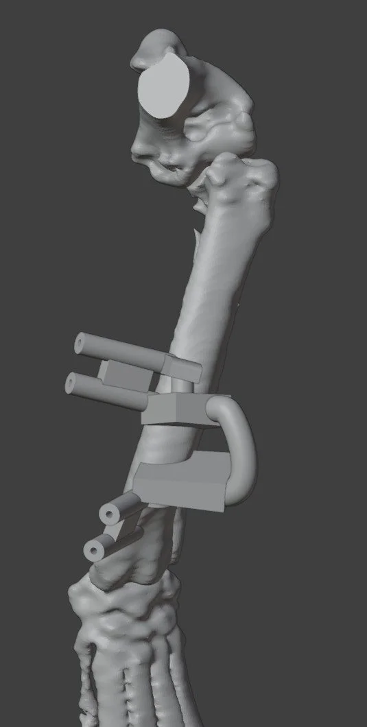
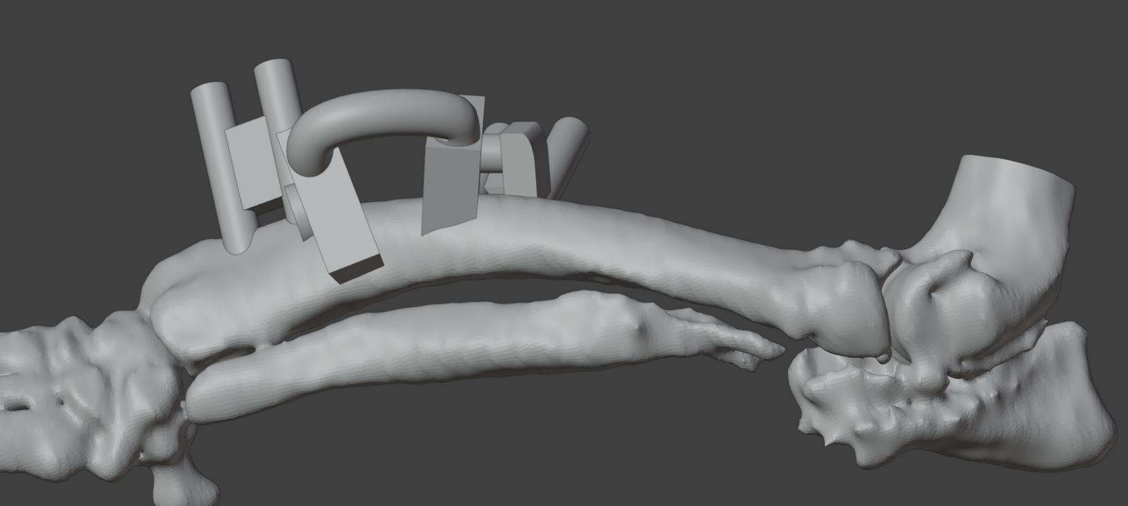
Images: Osteotomy guide seated on the bone model
Reduction Guide and Corrected Bone Model
Following the osteotomy, the next challenge was positioning the proximal and distal bone segments in their planned relationship.
The reduction guide was designed around the pin positions in the corrected configuration. Once the segments were aligned, the guide could slide along the pin axes to help maintain the planned reduction.
This linked the cutting and reduction stages: the osteotomy guide established the cuts and pin trajectories, while the reduction guide provided a reference for the intended relationship between the bone segments.
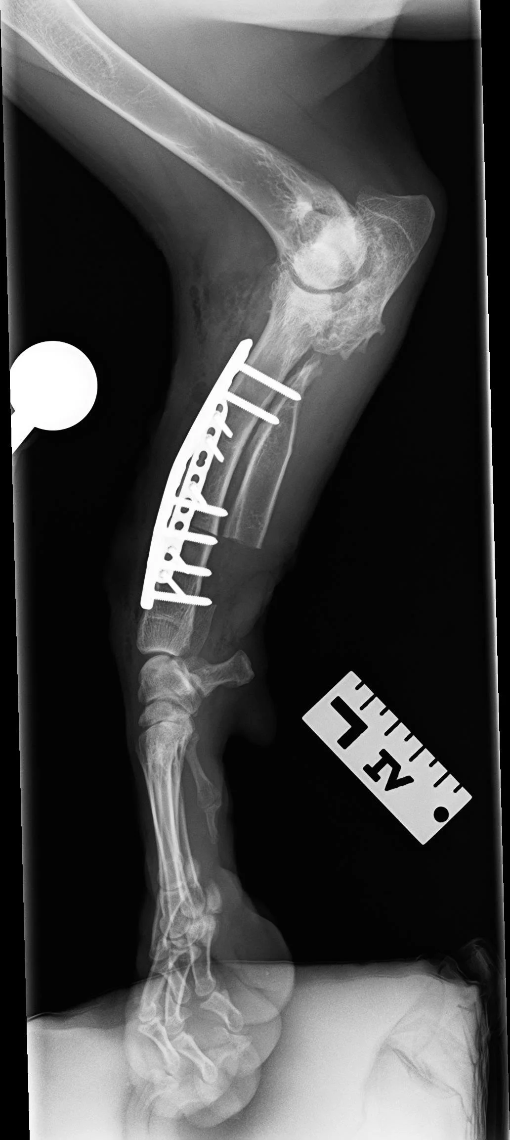
The planned construct also included a contoured 2.7 mm plate. The model sequence demonstrates the reduction guide supporting the corrected configuration during plate placement.
The corrected bone model shows the intended result of the digital plan. Comparison with the original model illustrates the planned changes in valgus, procurvatum and external rotation, and their effect on overall limb alignment.
Postoperative Imaging
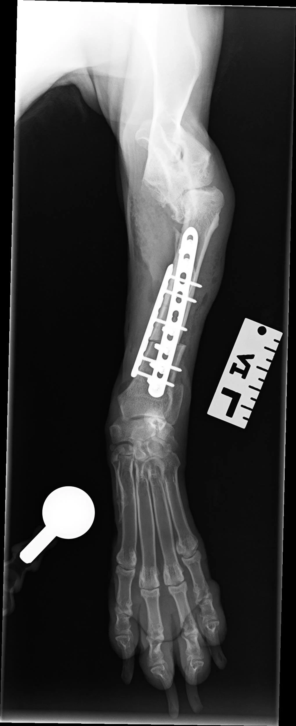
Postoperative radiographs supplied by ARH complete the case sequence, documenting the postoperative bone configuration and implant position.
Thank you to Dr. Sarah Goldsmid, Dr. Kyle Song and the ARH team for collaborating on Max’s case and providing the postoperative radiographs.